
How will industrial solar panels connect safely to the site’s electrical supply?
Industrial panels generate DC power, so we use correctly sized inverters to convert it before connecting the system to the site’s electrical distribution equipment. We assess the existing supply, install the required isolation and protection, then test the connection and confirm the system is safe to operate.
An industrial solar system connects safely when the generation equipment, site distribution system and grid connection are designed as one electrical installation. The panels produce direct current, which passes through the DC wiring and isolators to the inverters. The inverters convert it to alternating current that matches the site supply before it reaches the distribution equipment.
That connection needs more than a suitable spare way in a board. We consider how power flows around the site, how the switchgear is rated, what the network operator permits and what must happen if the grid supply fails.
The first check is the site’s existing electrical arrangement. An industrial building may have a three-phase supply, several distribution boards, a main switchboard, on-site generation or large motors that affect the design. We review the incoming supply, transformer arrangements where relevant, switchgear ratings, earthing and the proposed point of connection.
Your existing equipment must be able to accept the solar output without exceeding its rated current or interrupting capacity. We also consider fault levels and discrimination, so a fault in the solar equipment does not unnecessarily disconnect unrelated parts of the site.
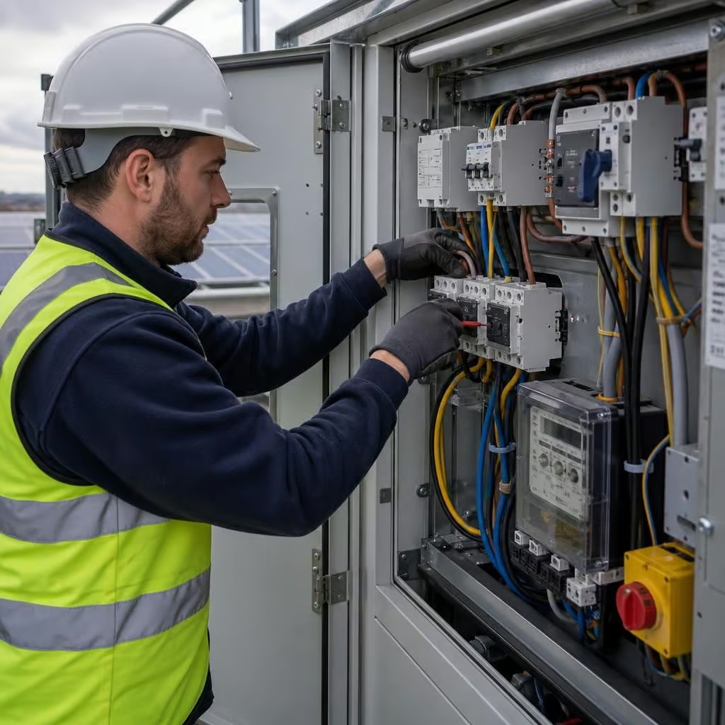
The solar output normally connects on the AC side through dedicated switchgear. This may include an AC isolator, circuit protection, metering equipment and a suitably rated connection into the site’s distribution system. The arrangement depends on the inverter output, the supply configuration and the distance between the plant and the switchboard.
Where the installation uses more than one inverter, we coordinate the individual outputs before they connect to the main board. That keeps the cable sizes, protective devices and switching arrangements appropriate for the combined generation rather than treating each inverter as an unrelated circuit.
The DC side needs its own protection and separation. Solar strings are grouped and routed so that cables can be identified, protected from mechanical damage and kept away from incompatible services. We select the correct DC isolators and surge protection for the array and inverter arrangement. Cable routes are planned to avoid unnecessary exposure to heat, water ingress and working-site damage.
DC circuits can remain live in daylight, even when the site supply is switched off. We label them clearly and arrange isolation points so engineers can work safely during maintenance. The location of those devices matters, particularly on a large roof or where the inverters are some distance from the panels.
Grid protection prevents the system from energising a failed network. The inverter monitors the incoming supply for voltage, frequency and other operating conditions. If the grid fails or moves outside the permitted range, the solar system disconnects rather than continuing to feed the network.
This anti-islanding function protects network workers and helps prevent unstable operation. It also means a standard grid-connected solar system will not keep the building powered during a mains failure. Maintaining power during an outage requires a separately designed backup arrangement, with suitable storage, changeover equipment and circuits.
The distribution network operator may need to approve the connection before work starts. The application depends on the system’s size, phase arrangement, export capacity and the characteristics of the site supply. Larger industrial installations commonly require an engineering review rather than a simple notification.
We establish the DNO requirements during the design stage. If export is restricted, the system may need an export meter or control equipment that limits energy sent to the grid. The control arrangement must respond to the site’s demand and keep the agreed export limit within the approved conditions.
That can be important where the site has a relatively small grid connection but a large roof area. The panels may still generate useful electricity for on-site equipment, while the control system prevents unwanted export when demand falls.
Connection design also covers earthing, bonding and surge protection. Solar equipment adds exposed equipment and long cable runs to an industrial site. We assess how the array, mounting system, inverter equipment and existing earthing arrangement work together. Surge protection is considered for both the AC and DC sides where the installation requires it.
The building’s lightning protection system, if present, must also be considered. The solar mounting system cannot simply be attached to existing protection conductors without checking the intended separation and bonding arrangement.
Safe installation depends on controlling the work at the switchboard. Connecting an industrial system can involve access to live-service areas, restricted plant rooms and equipment that cannot be shut down casually. We agree the isolation points and shutdown sequence with the responsible site contact before making the final connection.
Some work can be completed while the site remains operational. The final connection may still require a planned isolation of a board or section of the supply. We identify that requirement before work begins, so the site can plan around affected machinery, refrigeration, security systems or other critical loads.
Once connected, we check that the solar system responds correctly to the site supply and the agreed export arrangement. We confirm the switching, protection and monitoring functions and record the results for the building owner and relevant network or compliance records.
For a system intended to export electricity, MCS certification supports an application for the Smart Export Guarantee where the installation meets the scheme’s current requirements. We explain what information the owner needs to retain, including the generation and export metering arrangements.
The final result should be a clearly labelled connection that the site’s electrical team can understand and isolate. It should work with the existing distribution system, protect people and equipment during abnormal conditions, and leave the owner with a clear record of how the installation is connected and controlled.
A large site may have several distribution boards, but the nearest one is not always the right connection point. We compare the available boards, cable routes and local demand before choosing where the inverter output should join the supply.
That decision affects cable sizing, voltage changes and how evenly the three-phase supply carries the generation. It also leaves room for planned changes, such as a new production line or additional charging equipment. The result is a connection that suits the site’s electrical layout rather than simply fitting solar equipment into the first available board.
Discuss your industrial solar connection
If you’re assessing an industrial solar installation, talk to us about the proposed connection point, site demand and export requirements. We can review the existing electrical arrangement and explain what the connection will involve before you commit to the work.